A sprayer boom that folds slowly, a silage harvester header that shudders under load, a loader that drifts down overnight while the tractor sits idle — hydraulic faults almost never announce themselves as one dramatic breakdown. They arrive as slowness, weakness, drift, heat and leaking oil, and by the time the machine stops working you have usually lost field time and pushed contaminated oil through every precision clearance in the circuit.
The good news is that farm hydraulic systems are simple, repeatable and diagnosable with a pressure gauge. Almost every fault belongs to one of five families: not enough flow, not enough pressure, internal leakage, air or water in the oil, or excess heat. This guide gives you the fault-tree workflow used to sort them — classify the symptom, pressure-test the circuit, isolate the component — followed by the reference tables you need in the workshop.
Hydraulic System Basics — What Each Component Actually Does
Before you can isolate a fault you need to know what each part is responsible for. The critical mental model: the pump makes flow, not pressure. Pressure appears only when flow meets resistance. That single fact explains most "the pump is weak" misdiagnoses.
| Component | Function | Typical Failure Mode | First Symptom You Notice |
|---|---|---|---|
| Pump (gear / piston) | Moves a fixed volume of oil per revolution | Worn gear faces, scored body, worn pistons | Every function slow, worse when hot |
| Relief / safety valve | Caps system pressure, dumps excess back to tank | Stuck open (no pressure) or stuck closed (burst parts) | Nothing lifts, or hoses and seals fail |
| Directional control valve | Routes flow to the chosen cylinder or motor | Worn spool lands, cross-leak between sections | Drift, creep, wrong function moving |
| Cylinder | Converts oil pressure into linear force | Damaged piston seal, scored rod, bent tube | Weak lift, sinking under load, oil weeping |
| Accumulator | Stores pressure, absorbs shock, holds a charge | Lost nitrogen pre-charge, ruptured bladder | Harsh banging, no pressure held after shutdown |
| Filter / suction strainer | Traps particles before they reach clearances | Clogged element, collapsed or bypassing | Gradual slowdown, cavitation whine |
| Reservoir + breather | Holds oil, lets air and heat escape | Low level, clogged breather, water ingress | Foam, aeration, milky oil |
| Hoses & fittings | Carry oil between components | Age-hardened rubber, rubbed casing, loose BSP fitting | External leak, or a sudden burst under load |
The Three-Step Diagnostic Workflow
Step 1 — Classify the symptom into one family
Do not start by dismantling. Start by writing down exactly what the machine does and whether the fault is present cold, hot, or both — that last detail alone separates a viscosity problem from a mechanical one. Six symptom families cover nearly every field complaint: slow, dead, weak, drifting, juddering, and leaking. If the fault appears in only one function, the fault is local (that cylinder or that valve section). If it appears in every function, suspect the shared supply: oil level, suction strainer, pump or relief valve.
Step 2 — Pressure-test the circuit at the correct tap point
Connect a calibrated pressure gauge at the test port on the valve bank and record three numbers: standby pressure (all levers neutral), working pressure (function loaded), and deadhead pressure (function held against its stop, relief lifting). Compare deadhead against the relief setting in your manual. A system that reaches full relief pressure but still lifts weakly has a flow or internal leakage problem. A system that never reaches relief pressure has a pump, suction or relief problem.
Tools you need: a glycerine-filled gauge in the correct range (usually 0–250 bar or 0–400 bar), test tees and quick-couplers matched to your machine, a set of clean caps and plugs, an infrared thermometer, a stopwatch, and a clean drain bucket. Never substitute a tyre gauge or a compressed-air gauge — the ranges and fluid compatibility are wrong.
Step 3 — Isolate the component
Work downstream. Cap and plug individual sections of the valve bank to split the circuit; if the fault moves with the section you capped, the fault is inside that section. For a suspect cylinder, hold the load at mid-stroke, stop the engine, and time the rod creep per minute — measurable drift means the piston seal is bypassing. For the pump, compare measured flow at rated rpm against the specification. Replace nothing until one test proves one component guilty.
Symptom → Cause → Fix Reference Table
Use this as your fault tree. Find the symptom, confirm the cause with the test in Step 2 or 3, then apply the fix.
| Symptom | Most Likely Cause | Confirm With | Fix |
|---|---|---|---|
| All functions slow | Insufficient flow — worn pump, low engine rpm, wrong pump drive | Flow test at rated rpm; compare to spec | Rebuild or replace pump; restore correct rpm/drive ratio |
| Slow, worsening over weeks | Clogged suction strainer or return filter | Remove and inspect element; check ΔP indicator | Replace filter elements, clean suction strainer |
| Slow only when hot | Oil viscosity too low for the climate | Oil temperature over 80 °C; check grade fitted | Switch to ISO VG 68; clean cooler and radiator fins |
| Nothing moves at all | Relief valve stuck open, or no oil / suction blocked | Gauge reads near zero with pump turning | Bench-test or replace relief; refill, clear suction line |
| Nothing moves, pump silent | Pump drive coupling or input shaft broken | Pump input not turning with engine running | Replace coupling / shaft; inspect splines for wear |
| Weak lift, cannot hold load | Internal leakage — cylinder seals or worn spool lands | Pressure drops under load; leak-down test on cylinder | Reseal cylinder; replace spool or valve section |
| Load sinks / drifts down | Piston seal bypass, scored bore, worn spool | Time rod creep with engine off | Fit new seal kit; hone or replace barrel if scored |
| Jerky, juddering, creeping motion | Air in system, dirty oil, or water emulsion | Foam in reservoir; bleed screws spitting air | Bleed circuit, flush and replace oil and filters |
| Whining or growling noise | Pump cavitation from restricted suction or low level | Whine changes with oil temperature | Top up, clean suction strainer, check cold-flow rating |
| Oil overheating | Blocked cooler, continuous relief spill, internal leakage | IR thermometer at reservoir after 30 min work | Clean cooler, set relief to spec, repair leaking components |
| External leaks at joints | Hardened O-rings, loose fittings, cracked hose cover | Wipe clean and watch for weeping under pressure | Torque to spec with new seal; replace hose, never tape |
| Functions cross-talk / wrong cylinder moves | Valve bank cross-leak, or hoses plumbed incorrectly | Cap each section in turn; verify against schematic | Repair or replace valve section; re-plumb to schematic |
| Oil milky or creamy white | Water ingress — condensation, washing, leaking cooler | Oil on dipstick looks like coffee with milk | Drain, flush, refill, replace breather, seal the water source |
Hydraulic Oil: Grade, Cleanliness and When to Change
Choosing the right oil prevents more breakdowns than any repair. Viscosity must be high enough at working temperature to seal clearances, yet low enough when cold to flow into the pump without cavitating.
| Application / Climate | Grade | Ambient Range | Notes |
|---|---|---|---|
| Tropical: Africa, SE Asia, South America | ISO VG 68 | 30–45 °C | Standard for most farm machinery in hot climates |
| Temperate / mixed seasons | ISO VG 46 | 10–30 °C | Most common factory-fill grade |
| Cold winter starting | ISO VG 32 | -10–15 °C | Only for genuinely cold climates; monitor leakage when hot |
| Cleanliness target (ISO 4406) | 18/16/13 | All | 17/15/12 for circuits with sensitive proportional valves |
| Filtration | 10 µm absolute | All | Pressure-line element; 25 µm return is common on older machines |
Decide an oil change using three independent methods and act on whichever fails first: (1) hours — typically 1000–2000 hours or annually; (2) oil analysis — water above 0.1%, viscosity shifted more than 10% from new, or a particle count outside the ISO 4406 target; (3) field observation — oil that is black, smells burnt, holds foam after shutdown, or has turned milky. Never judge oil by colour alone — a dark oil can be perfectly serviceable and a clear oil can be full of water.
| Element | First Service | Normal Interval | Replace Early If |
|---|---|---|---|
| Suction strainer | 50 h | Clean every 250 h | Cavitation noise, low flow at startup |
| Return filter | 50 h | 500–1000 h | Clogging indicator in the red zone |
| Pressure filter | 50 h | 500 h | ΔP alarm, or after any pump/valve failure |
| Breather / filler cap | — | 1000 h | Oil emitting an aerosol mist or pressurising the tank |
| Full oil charge | 50 h | 1000–2000 h or 1 year | Oil analysis fails any of the three tests |
Pressure Testing: Safety Comes First
⚠️ High-pressure injection warning: hydraulic oil escaping at 150–250 bar can penetrate skin through work gloves and look like no more than a small scratch or bruise. The injury is serious: within hours it causes deep tissue necrosis and can lead to amputation if untreated. If oil penetrates your skin, go to a hospital immediately and tell the medical team it is a high-pressure hydraulic injection injury. Do not wait to see whether it hurts. Cardboard, cloth and even thin leather are no protection — always use a piece of cardboard, never your hand, to search for a pressurised leak.
Beyond injection injury, respect two more hazards. Hot oil burns: a circuit that has been working for an hour can hold oil above 80 °C, so wear gloves and eye protection and let the machine cool. Stored energy: accumulators hold pressure after shutdown — discharge them per the manual before opening any line, and cycle all control levers to neutral with the engine off to dump residual pressure before disconnecting a quick-coupler.
Test procedure in short: machine on level ground and braked, engine off, controls cycled, accumulator discharged. Fit the gauge at the specified test port using clean adaptors. Start the engine and let the oil warm to working temperature. Record standby, working and deadhead pressures. Then shut down and vent the gauge before removing it. Write the three numbers in the machine log — a pressure trend across a season tells you a pump is wearing long before it fails.
Replacing Cylinder and Valve Seals — Standard 8-Step Procedure
- Depressurise and isolate. Engine off, ignition key removed, all levers cycled, accumulator discharged. Fit a lockout tag so nobody starts the machine while you are working on it.
- Clean before you open. Pressure-wash the machine and the surrounding area a day earlier if possible, then wipe the work area with lint-free cloth and cap every open port immediately after opening.
- Remove the cylinder or valve and drain it. Note the orientation of the end cap, the position of any shims, and the exact routing of hoses before you disconnect them — photograph it.
- Inspect bore, rod and gland. Look for scoring, pitting, rust and chrome flaking. A cylinder with a scored bore or a bent rod must be honed, re-chromed or replaced — new seals alone will leak again within days.
- Remove the old seals without scratching metal. Use brass or plastic picks, never a screwdriver. Clean every groove until it is spotless and dry, and check that the drain holes in the gland are clear.
- Fit the correct seal kit correctly. Match material to the fluid (NBR for mineral oil, FKM for high temperature), check that lip direction and backup rings face the right way, and lubricate every seal with clean hydraulic oil before assembly.
- Reassemble to torque specification. Use a torque wrench on end caps and fittings, apply thread sealant only where specified, purge air at the bleed points, then test at low pressure first and look for weeping before going to full load.
- Recheck after one hour of work. Re-torque fittings, inspect for weeping, top up the reservoir and record the repair in the machine log.
Five Common Mis-Repairs and Their Consequences
| Mistake | Why It Seemed Reasonable | What Actually Happens | Correct Action |
|---|---|---|---|
| Topping up with engine oil or a different grade | "Oil is oil, and I need the machine working today" | Wrong viscosity, seal swell or shrink, foaming, faster pump wear | Keep the correct grade in stock; top up with the same spec only |
| Working with open ports and a dirty funnel | Faster than cleaning first | Particles score the pump and valve lands within hours of startup | Cap every port, clean every funnel, flush after any contamination event |
| No torque wrench on fittings | "Tight is tight" | Cracked housings, stripped threads, crushed O-rings and new leaks | Torque to the manual value with a calibrated wrench |
| Cracking a joint with the system pressurised | Trying to find a leak quickly | Oil injection injury, oil loss, air entrained through the whole circuit | Depressurise, use cardboard to probe for leaks, then open the joint |
| Turning up the relief valve for more power | "It lifts more now" | Burst hoses, cracked cylinders, failed pump, overheated oil and burned skin | Set relief to specification; repair the pump, seals or valve instead |
Preventive Maintenance Schedule
Ninety percent of hydraulic breakdowns trace back to a skipped interval. This schedule is written to be copied into your workshop wall chart; adjust the hour figures to the manual for your specific machine.
| Interval | Check | What Good Looks Like |
|---|---|---|
| Daily | Oil level, leaks, hose condition, noise | Level at the sight glass with machine level and cold; no wet spots on fittings, no rubbed or cracked hose covers, no whine or rattle |
| Daily | Clean fittings and check weeping | Wipe each fitting dry; no fresh damp film after an hour of work |
| 50 h | Torque check, breather, cooler fins, foam check | All fittings at spec torque; breather clear; cooler fins free of chaff and dust; no foam in the reservoir |
| 250 h | Suction strainer, return filter, relief setting | Strainer clean with no metal debris; filter element replaced; deadhead pressure at the manual value |
| 250 h | Accumulator pre-charge (per manufacturer) | Pressure held after shutdown and released only through the correct procedure |
| 1000 h / annual | Full oil change, all filter elements, oil analysis | Fresh oil at the correct grade, particle count inside the ISO 4406 target, water below 0.1% |
| 1000 h / annual | Pressure and leak-down test every circuit | Deadhead pressure at spec, rod creep below the manual limit on every cylinder |
| 1000 h / annual | Replace hoses older than 6 years; reseal drifting cylinders | No age-hardened rubber in service; no function drifts after 30 minutes under load |
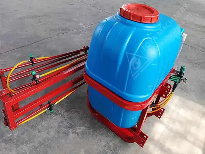
Machinery with heavy hydraulic duty — a self-propelled harvester's header and steering circuits, a hydraulic sprayer boom, a TMR mixer door and auger drive — repays this schedule in-season. If your fleet includes any of these, browse the self-propelled silage harvester, the tractor mounted boom sprayer or the TMR feed mixer product pages for standard hydraulic specifications and spare-part lists.
Hydraulic Troubleshooting — FAQ
How do I know whether the pump or the relief valve is faulty?
Dead-end one function and read the pressure gauge. If the gauge climbs to the relief setting and holds, the pump is producing flow and the relief valve is working — your loss is downstream. If pressure stays far below the relief setting, cap the pump outlet and test again: pressure still low means a worn pump; pressure normal at the pump but low at the valve bank means internal leakage in the valve, hose or cylinder. Always test with a calibrated gauge and a clean test tee, never by feel.
Can I use ISO VG 46 instead of VG 68 in hot weather?
No — that is backwards. ISO VG 46 is thinner than VG 68. In tropical ambient temperatures of 30–45 °C, VG 46 thins further once the oil reaches 70–80 °C working temperature, so internal leakage rises, response gets spongy and wear accelerates. Use ISO VG 68 (or the grade in your manual) for hot climates, VG 46 for temperate conditions, and VG 32 only for cold starting. Never mix grades to "make up" the level.
Why does my hydraulic system overheat?
Three causes cover most cases: a blocked oil cooler or radiator (clean the fins and check airflow), continuous oil spilling over the relief valve because the circuit is dead-headed or the relief is set too low for the load, and internal leakage converting pressure into heat. Check oil temperature with an infrared thermometer at the reservoir after 30 minutes of work — above 80 °C is a fault, not normal.
How often should I change hydraulic oil and filters?
On a new machine, change oil and filters at the first 50 hours. Afterwards, clean the suction strainer every 250 hours, replace return and pressure filter elements every 500–1000 hours or when the clogging indicator shows, and change the full oil charge every 1000–2000 hours or once a year, whichever comes first. If the oil fails analysis — water above 0.1%, viscosity shifted more than 10%, or visible particles — change it immediately regardless of hours.
My hydraulic oil turned milky white — can I still use it?
No. Milky or creamy oil is an oil-water emulsion, and water destroys the oil film that protects pumps and valves: it causes rust, accelerates wear and can freeze in cold weather. Drain the system completely, flush with a small charge of fresh oil and drain again, replace all filter elements, reseal or replace the breather, and find the water source — usually condensation from temperature cycling, high-pressure washing, or a leaking cooler.
Is it safe to turn up the relief valve for more lifting power?
No. The relief setting protects every component in the circuit. Turning it up to lift a heavier load usually ends with a burst hose, a cracked cylinder barrel, a blown shaft seal or a failed pump — and hot oil sprayed over the operator. If the machine cannot lift a load it used to lift, the fault is a worn pump, worn cylinder seals or a mis-set relief, all of which are diagnosed with a gauge. Restore the specification value and fix the real cause.
Still Chasing a Hydraulic Fault?
If your circuit is not covered here, or the repair is beyond basic workshop tools, FOYA Machinery's after-sales team can help you narrow it down. Send us a short video showing the symptom, your machine model, and the three pressure readings you recorded — standby, working and deadhead — and we will point you to the likely component and the correct replacement part.
Browse our silage harvester, boom sprayer and TMR feed mixer pages for hydraulic specifications, or contact us for seal kits, filter elements and hoses.
Contact us for hydraulic spare parts, seal kits, diagnostics and support.